Part of the Oxford Instruments Group
Expand
Collapse
Part of the Oxford Instruments Group
30 July 2020 | Stephanie Baclet
Manufacturing slanted surface relief gratings (SRGs) has unique challenges compared to conventional vertical grating.
Manufacturers have to gain tight control over manufacturing tolerance in order to ensure that the simulated optical efficiency of the waveguide design is delivered by the fabricated product.
Based on our expertise in etching slanted gratings for augmented reality (AR) applications, we share our top 3 requirements to demonstrate high quality slanted features.
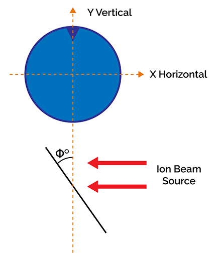
Due to the slanted structure, the process is highly subject to ion deflection which results in asymmetric etching and therefore loss of control over the angle.
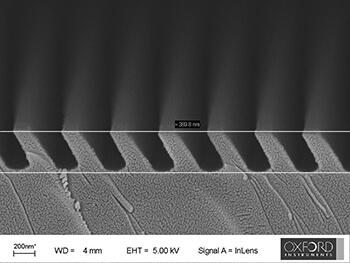
SEM image of SRGs for AR applications.
However, not all techniques are equals. Many techniques based on plasma technology are either complex, costly or cannot guarantee a good etch rate and profile uniformity over a large area.
Ion beam etching offers the best way of providing physico-chemical etch directionality. Ion beam processing operates at much lower gas pressures than other plasma techniques. This allows for less gas scattering and better profile control.
AR grating for SRGs.
The target uniformity across the wafer is defined by the requirement of the application which includes the waveguide size, and number of waveguides per wafer.
However, depending on the design on the etching reactor, the area matching the target uniformity might not correspond to the full wafer size. The edge exclusion can be as large as 40mm. The large edge exclusion results from non-uniform ion distribution.
When dry etching at an angle, the etching depth tends to be higher in the area closer to the ions source. Equipment manufacturers have to manipulate the ions' distribution to compensate for the non-uniformity.
The periodicity of the features depends on the application. For AR headset, the typical period for waveguide combiners is around from λ/2 to λ which results in groove around 100 to 200nm. These dimensions require the use of finer lithography equipment such as E beam lithography or Nano imprinting.
Without clearly defined mask structure, defects can be transferred to the features during process. It is therefore critical to characterise the profile of the mask before etching.
Common SEM characterisation can be used to image the mask however the evaluation has to be done on the full surface of the wafer. Once the mask processing is well understood and controlled, optimum yield can be achieved during the slanted etching process.
If you would like to learn more on processing slanted features, take a look at our AR Solutions.

Stephanie Baclet
Senior Technical Marketing Engineer


2020
2019
© Oxford Instruments 2026