Part of the Oxford Instruments Group
Expand
Collapse
Part of the Oxford Instruments Group
Below you will be able to find the first part of experimental results with chemically assisted etching which our expert Dr Sebastien Pochon presented at SPIE conference in San Jose, California last week.
The need for forming gratings (for example used in VR headsets) in materials such as SiO2 has seen a recent surge in the use of Ion beam etching techniques. However, when using an argon-only beam, the selectivity is limited as it is a physical process.
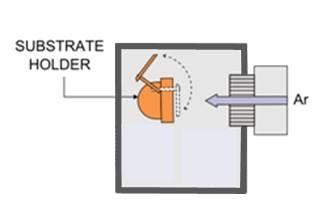
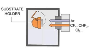
Typically, gases such as CHF3, SF6, O2 and Cl2 can be added to argon in order to increase selectivity; depending on where the gas is injected, the process is known as Reactive Ion Beam Etching (RIBE) or Chemically Assisted Ion Beam Etching (CAIBE). The substrate holder can rotate in order to provide an axisymmetric etch rate profile. It can also be tilted over a range of angles to the beam direction. This enables control over the sidewall profile as well as radial uniformity optimisation. Ion beam directionality in conjunction with variable incident beam angle via platen angle setting enables profile control and feature shaping during nanopatterning. These hardware features unique to the Ion Beam etching methods can be used to create angled etch features.
One of the advantages of ion beam etching is that the ion energy and flux can be independently controlled via the voltage applied to the screen grid and the plasma density (determined by the RF power).
In idle mode the ion beam chamber reaches base pressures below 2E-7 Torr, pumped by a 1600 litre/sec turbomolecular pump backed by a 100 m3/hour dry pump. During ion beam etching processes, the chamber pressure typically reaches values between 2.5 and 6E-4 Torr. This means that the ion beam is highly directional being in an essentially collisionless environment with a mean free path > 20 cm, greater than the distance between source and substrate. It is beneficial that the ion source and neutraliser can run stably with a total flow in the range 10-20 sccm to keep the pressure low. The ion current obtainable from each aperture hole of the grids is limited by space charge. This is described by the Child-Langmuir law as a function of the gap between grids and potential difference between them, in this case, the screen and accelerator grid1.
However, because it is a physical process, when etching patterns using a mask such as photoresist, the corresponding selectivity or etch rate ratio between the etched material and photoresist mask is below 5:1, and is often around 1:1.
Selectivity to the mask can be enhanced by adding gases such as CHF3, SF6, N2, O2 and Cl2.
Depending on where the gas is injected, directly into the source or into a gas ring located in the vicinity of the sample, the techniques are respectively known as Reactive Ion Beam Etching (RIBE) or Chemically Assisted Ion Beam Etching (CAIBE). Using suitable chemically reactive gases can improve etch rates and selectivity to mask material. Indeed, in RIBE mode, the reactive gases are partially dissociated inside the ion source, and some will be ionised and accelerated to the substrate, while in CAIBE mode, most of the gas impinging on the substrate is not dissociated, and only noble gas ions bombard the surface.
As in plasma etching, careful selection of inert and reactive gas ratios allows for example the sidewall profile to be controlled. This will also depend upon the choice between the material and the mask being etched.
The substrate holder or platen can be tilted between -90°, the loading position, and up to about +65°. Tilt provides further control over the sidewall profile as well as radial uniformity optimisation.
The substrate holder can rotate up to 20 rpm in order to provide an axisymmetric etch rate profile. The substrate is cooled by a dedicated chiller and helium is used as a conductive medium to transfer heat for cooling during etching. Its purpose is to keep wafer temperature as low as possible during etching processes in order to preserve the quality of the resist. For other processes, a heating element imbedded within the platen allows the substrate to be heated to temperatures as high as 300°C. Other mask that are not sensitive to temperature can be used, SiO2 or Si3N4. Figures 1a, 1b and 1C below show the chamber layout for IBE, RIBE and CAIBE mode.
When etching with argon only, in IBE mode, the common artefacts are trenching, fencing and rough surfaces. Trenching normally appears at the edges of the etch profile; this is because of a “double dose” effect of ions near the sidewall due to beam divergence and reflection from the walls.
Fencing is the caused by etched material that was re-deposited on the sidewalls of the mask. Rough surfaces are usually caused during etching of polycrystalline substrates.
Some other effects that can found after IBE etching process, such as ending up with positive slope etched material or faceting. This is linked with the mask quality. This can be achieved in a single process step where the platen rotation is set to 20 rpm and set to a fixed angle of 30°.
It can also be done in two separate steps. In the first step, the platen angle can be set to a shallower angle like 10° where ninety per cent of the etching process takes place. In the second step, the platen angle is set to a higher angle like 45° or higher, depending on the sample geometry and in order to avoid shadowing, for the remaining ten per cent of the etching process to clean the sidewalls. When etching at normal incidence, Ar+ ions momentum is transferred with every collision; on average about one atom to two atoms are removed per one incident ion. Ions penetrate deeper sharing their energy with many atoms. As regards the sample surface temperature, this means that more heat is transferred to the sample and photoresist.
This is a typical outcome when trying to etch as fast as possible. The key is to maintain the sample surface and photoresist mask at a low temperature using a technique such as helium back side cooling. Etching at higher angles increases the yield, where one ion can remove up to five atoms. The energy is transferred nearer to the surface; hence more atoms are ejected.
Ion beam directionality, in conjunction with variable incident beam angle through platen angle setting, enables profile and sidewall control and feature shaping during nanopatterning. In RIBE and CAIBE mode, the patterning process does not rely solely on a physical component (sputtering) but a chemical one too. The chemical enhancement enables, when compared to pure physical etching, a better selectivity and higher fidelity of pattern transfer thus limiting CD losses or surface roughening. Moreover, the sample surface temperature is a very important parameter to control, because it will determine the isotropic component of the etch process. Indeed, in some processes, the temperature becomes a critical parameter as it will have a significant effect on the volatility of the etch products and hence can dramatically increase the etch rate. The issue then becomes controlling the verticality of the etch profile.
For more information on Ion Beam technology, visit our website or drop us a line through our email plasma-experts@oxinst.com and I will be happy to share my expertise and information with you.
Author: Dr Sebastien Pochon
reference 1 Goebel, D. M. and Katz I., “Fundamentals of Electric Propulsion: Ion and Hall Thrusters,” John Wiley & Sons, Inc., Chapter 5 (2008).

© Oxford Instruments 2026